
A quick guide presenting a simple system for managing furnace waste gases. The system here uses a temporary holding tank to cool the waste gases before sending them on to your atmospherics processing system elsewhere. Basic logic kits make it all automatic and hands-off.
Table of Contents
Introduction
Note: Credit goes to Rattlehead
The purpose of this guide is to present a simple system for managing furnace waste in Stationeers. The furnace tends to output gasses at temperatures that are dangerous to send into your atmospherics storage system, but some of those gasses are valuable and we want to keep them. To that end, we need to capture those gasses, hold them until they’re cooled to a safe temperature, and then send them on to our processing facility afterward.
This system could be used for managing any hot gasses that you want to cool prior to moving them into your main atmospherics process. With some adjustments, the system could likely be modified for warming gasses if you were on Europa and had a hot room to warm the radiators in.
I hope to write this in a way that is understandable to anyone. If you’re an old hand at Stationeers logic kits, you’ll probably grok the system just by a cursory glance at the pictures. But, I intend to make this guide understandable even to completely new players, if I can. Please feel free to ask for clarifications if anything is confusing or unclear.
A few caveats:
- I’m sure there are more compact, more advanced, or more efficient ways to do this. This is just a simple build with logic kits.
- This system doesn’t cover setting up your furnace; that’s beyond the scope of this guide. I will say that you should be able to just run a pipe from your furnace output connection (advanced or regular) into this system with no problems (as long as you don’t exceed the pipe pressure limits).
- This guide assumes that you have a central storage tank elsewhere where you keep gasses prior to filtration for use. That tank is where the volume pump in this guide is assumed to be sending your cooled furnace exhaust.
With that out of the way, let’s get started!
Plumbing The Pipes
The overall goal here is to capture the waste gasses from the furnace, hold them safely until they are cooled, and then send them on to our atmospherics process elsewhere. That means we’re going to need the basic piping done up first.
What you’ll need:
- Pipe – lots of pipe.
- Several radiators – more radiators means faster cooling.
- A Kit (Tank). One should do nicely.
- A Volume Pump.
Your setup will vary depending on your needs and your build. Here’s what mine looks like:
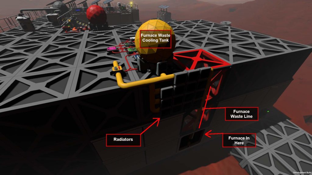
(Clicky to embiggen.)
The image is a bit dark on the side of the building due to the shadow, but hopefully you can see that all of the plumbing is simply connected together. The output from the advanced furnace inside the building simply runs up the side, branches into multiple lines to mount the radiators, connects to the tank, as well as a line going to the volume pump.
That’s really all there is to it, as far as the plumbing goes. However, do keep in mind that the area around those radiators will get hot. Don’t set those up anywhere near where you keep stuff you don’t want melted.
Now on to the logic.
Wiring It Up
This is the meaty bit. It might seem complicated at first, if you’re new to working with Stationeers logic kits. We’ll go through it piece by piece and it should all make sense in the end.
To begin with, we need to think about exactly what we want our system to do. Very simply, we have a volume pump to control and that’s it – everything else is passive and doesn’t need any input. We want this pump to stay off until two conditions are met:
- The temperature inside the tank must be below a certain value.
- The pressure inside the tank must be above a certain value.
We don’t want the pump to let hot gasses into our atmospherics process, and we don’t want the pump to run when the tank and waste lines are empty.
Here’s the parts you’ll need:
- A buttload of cable – seriously, I go through that stuff so fast.
- 3 Kit (Logic Memory)
- 3 Kit (Logic I/O)
- 4 Kit (Logic Processor)
- Your Labeller – Handy for setting memory values and a must for giving logic kits useful names.
Optional: If you want to isolate this system from the rest of your circuitry, drop down an Area Power Controller to power all this. This has the added benefit of a battery backup if the power feeding it goes down.
Let me present the layout, and then I’ll go through each type of item in turn. Note that the tank, pump, and all the logic kits are just simply all connected to each other. Don’t forget to connect the tank’s data connection and the volume pump into the wiring shown here.
Here’s how mine looks:

(Ignore the toes – those are optional.)
Now, your layout doesn’t have to be exactly like this. The positioning isn’t that important. What is important is that each device has a clear connection to all* of its ports and they can all “see” each other on the network. Lay them out however you have room and in whatever fashion helps you keep it all straight.
*Note: The Logic Memory has ports on each end, but only one needs to be used on those. However, they can’t “pass through” data to other devices. A connection on each end is not contiguous.
So, let’s go through each of these devices one by one…
The Memory Kits
Mem 1, Mem 2, and Mem 3 all just store values we’ll need for comparisons on other logic kits. You can do them in whatever order you like, just make sure that you set their values correctly and give them names that make sense so you can find them later when setting up your Logic Compare kits.
In my setup, Mem 1 holds the maximum temperature we want to allow – the pump will stay off until the gasses cool to below this value. Stationeers logic kits and other devices use Kelvin temperatures. In my case, I went with a value of 298.15, which is about 25 C. If you need a quick conversion from C to Kelvin, just pop over to Google and type in whatever temperature you want to convert, followed by “C to K”. Note that H2 and O2 mixes in Stationeers will combust at around 32 C.
Mem 2 holds the value for the minimum pressure we want to allow. If the waste system gets below this pressure, the pump will cut off. This keeps us from running the pump when the system is empty. This is in Kpa and I have mine set to 0.5.
Mem 3 is very simple. It holds a value of 1. We’ll be using it later to make sure both of our conditions are met for turning on the pump.
The Logic I/O Kits
The three Logic I/O kits are used to pull data from, or write data to, other devices on the network. Most devices have various values we can read from them, but you normally can’t access those values without a Logic Reader to pull it out for us.
The first two I/O kits need to be placed as Logic Readers. One of them will read the tank pressure. Set its left screw (IN) to whatever you named your waste tank, and set its right screw (VAR) to “Pressure”. Go ahead and activate the little red button on the kit to turn it on. Now, when you look at this logic reader, the tooltip that pops up should show you the tank’s current pressure in Kpa.
The second Logic Reader is very similar. Set its input to the tank, and set the VAR to the “Temperature” variable. Remember to use your labeller to give the Logic Readers names that make sense.
Finally, we need one I/O kit set down as a Logic Writer. This one will actually turn the pump on and off, but we’ll come back to it later. For now, just plop it down in the network and name it “Pump Power Logic Writer” or some other useful name.
A note on Logic Kits: Whenever you make adjustments to a Logic Kit, the safe thing to do is turn it off first. While using your screwdriver to cycle through the various settings (particularly on Logic Writers) if the kit is still turned on, it’s still doing its thing. This could result in unexpected changes in settings of other devices as you make your adjustments.
The Logic Processor Kits
The Kit (Logic Processor) gives us the last two types of kits we need. We need three of these placed as Logic Compare kits, and the fourth one placed as a Logic Math. (Note that this is the Math Unit, not Unary Math Unit.)
The Logic Compare kits have two inputs and one output. They take the two values from their inputs, compare them depending on how they’ve been set, and then output a 1 or a 0, depending on if their compare results in a “true” or “false” result.
First, set one to compare the temperature. Give it a useful name, “Max Temp Compare” or something like that. Set its left input (1) to the Logic Reader that is pulling the temperature value from the waste tank. Set its right input (2) to the Logic Memory storing the max temperature value we want to allow. Finally, set the middle screw (OUT) to “Lesser”. Now, when the Compare Kit is turned on, it should show a 0 or a 1 depending on if the tank’s contents are cooler or hotter than the value we set in the Logic Memory device. If the temperature is below our max temp, this Logic Compare will give us a 1 – we’ll need that value soon.
The second Logic Compare is set up very similar to the first, but to check if the tank pressure is above our minimum value. Set its left input (1) to the Logic Reader that’s pulling the pressure reading from the waste tank. Set its right input (2) to the Logic Memory holding our minimum pressure value. Finally, set the operation (OUT) to “Greater”. Turn it on and we should see a 1 or 0 on this kit depending on if the tank’s pressure is above our minimum pressure setting or not.
So, now we have our two conditions for turning on and off the pump. We just need to bring them together. Before we get to the third and final Logic Compare, let’s visit that Logic Math kit.
What we want to do is make sure that both of our conditions are met. That means that, if we’ve set everything up properly, both of our Logic Compare kits are reading a value of 1 – both conditions are met to turn on the pump. So, to combine these into a useful value, we’ll add them together. That’s what we’ll do with the Logic Math kit. Set its left input (1) to the Logic Compare that’s checking the pressure. Set the right input (2) to the Logic Compare that is checking the temperature. Set the operation (OUT) to “Add”. This will add the values from the two compare units, giving us a result of 0, 1, or 2. If neither condition is met, we have a 0, if one (pressure or temperature) is good but the other is not, we have a value 1, and if both conditions are good, we have a 2.
But, our pump needs a binary choice. Either it’s on, or it’s off. To get a result we can use, we go to our last Logic Compare kit. Remember that third Logic Memory kit – the one that’s just storing a value of 1? Here’s where it comes in.
Our last Logic Compare takes the result from our Logic Math on its left input (1). The right input (2) is set to the Logic Memory with a value of 1. Set the operation (OUT) to “Greater”. Now this Logic Compare will read a 0 unless both of our conditions are met for turning on the pump. If both conditions are met, the Logic Math kit will read as a 2, which is greater than the 1 stored in our memory kit, and this Logic Compare will output a 1.
The Final Tweak
So, we’ve finally gotten down to a single value. A simple yes or no answer (in binary fashion) to the question of whether both of our conditions are met to turn on the pump.
All that’s left is to tell the pump what to do. For that, we go back to that Logic Writer kit we put down earlier. As you might expect, it’s similar to the Logic Reader. We set it to a particular device and we choose a variable to interact with. But, of course, we’re writing to the device rather than reading information from it.
The Logic Writer has three screws to adjust. Set its left screw, the input labeled (IN) to point at that last Logic Compare (the one that checks if the math result is greater than 1). Now the Logic Writer will be getting either a 0 or a 1 from that Logic Compare.
Set the screw on the upper right (OUT) to the Volume Pump. Now we can tell it what variable on the pump we want to write to. Set the lower right screw (OUT VAR) to the pump’s “On” variable.
Now we’re all set. Take a last check. Make sure all of your values are set correctly. Check that you’re getting the expected results from your Logic Compare units. Are all the memory kits set to the correct values?
Once everything is verified, make sure all the kits are turned on, then turn on the Logic Writer. We should be good to go!
Time to head back to the hab for well-deserved baked potato and some time in the sleeper…

Be the first to comment